The article below deals with the installation of the original tiltBoard and is left for historical reasons. You can download instructions for the new Talismoon tiltBoard 360 by clicking here (PDF).

In this tutorial I am going to take you through installing a tiltBoard into an Xbox 360 Wireless Controller. I am going to be hacking into the left analog stick. If you want to do the right analog stick, the wiring will be the same, but it will be on the right stick instead. I will also be installing a DPDT switch for switching the input into the controller between the tiltBoard and analog stick. Instructions are also provided for those who do not want to install a switch. I apologize for some of the blurry pictures. At the beginning of this tutorial I was using an old digital camera, and towards the middle I switched to my new Canon PowerShot SD600 6MP Digital Elph Camera, which has been working great! Click on any of the pictures throughout the tutorial for a larger version.
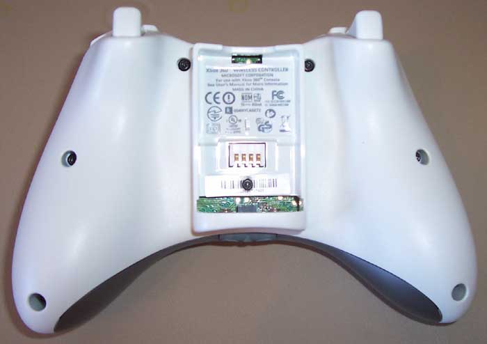
In the wired version of the controller, Microsoft just used standard Phillips screws, but in the wireless version they went with Torx T8 security screws. In order to take these out I bought a VTBT5 33 Piece Security Bit Set. It came with a T8 security bit and worked great for taking out the top 5 screws. However, the bottom two screws are very deep inside of the controller and my bits were not long enough to reach. In order to get them out I ended up using a small flathead screwdriver to break off the security pins and used a regular Torx T8 bit. You can also take them out with a flathead screwdriver of the right size, so you have several choices.
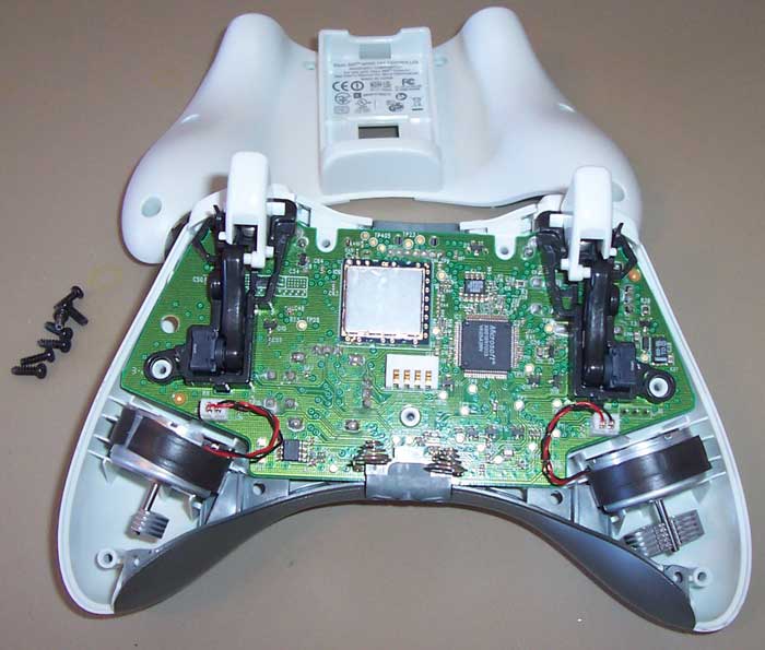
After the cover is off the vibrating motors need to be removed. Just be careful and try to pull on the connector and not the wire. About half the time the connector will come out like it is supposed to, and the other half of the time the female end of the connector will pull off of the board leaving 2 pins sticking up. If the connector gets pulled off of the board don’t worry, it will still work. In the picture below I had one connector come out correctly and one I pulled off of the board. Note that the two vibration motors are different sizes. One is smaller than the other. To make sure I put it back together correctly I wrote a “S” on the smaller motor side.

To get the circuit board out of the controller shell, push up on the analog sticks. With a little wiggling both the circuit board and the gray piece will pop off.
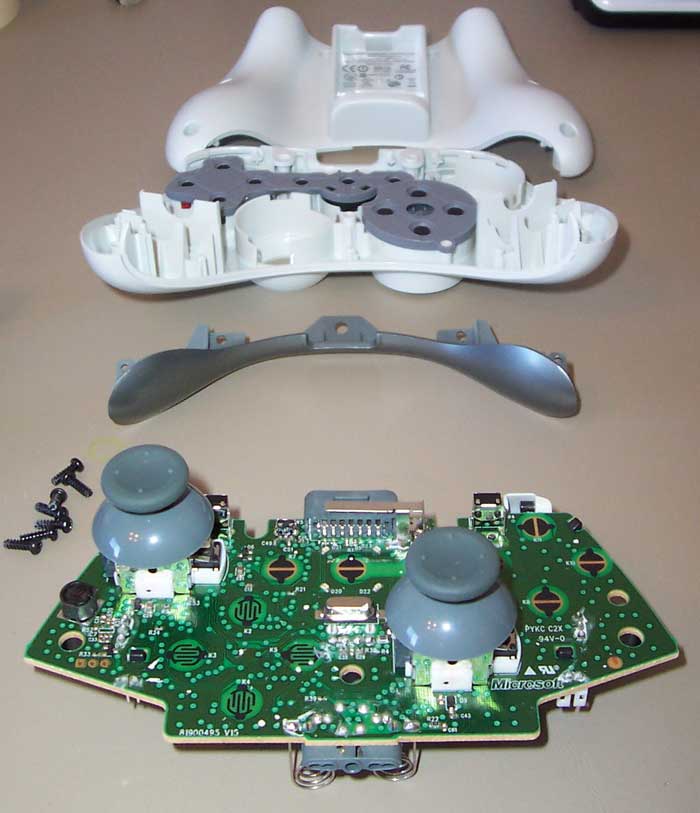
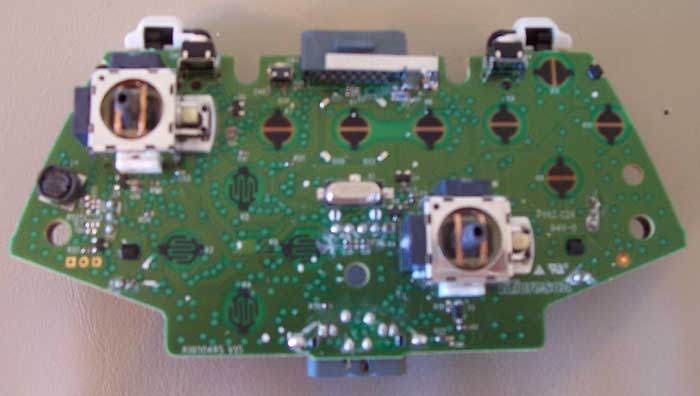
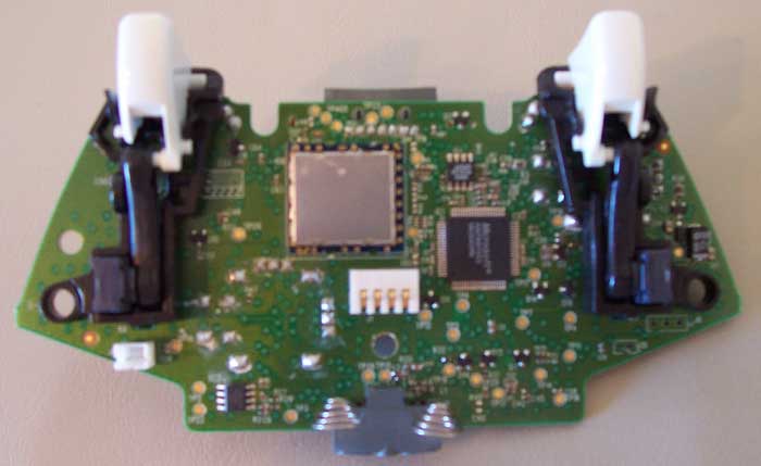
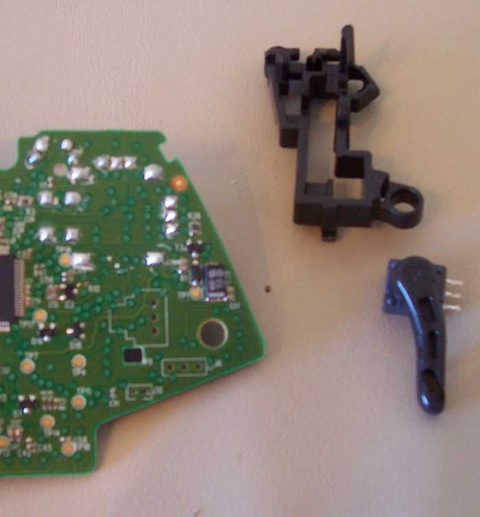
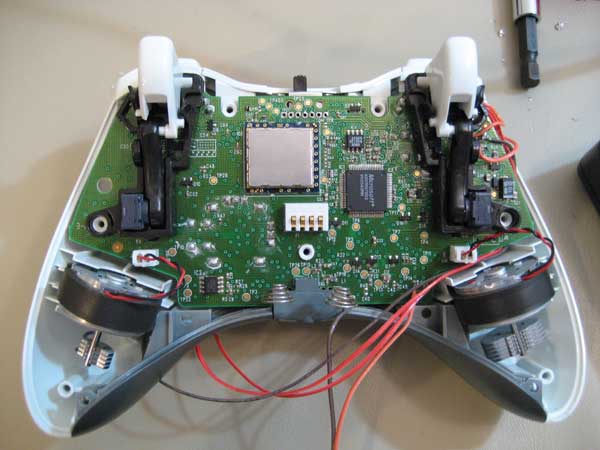
The analog stick tops will just pull off. Now you should have the circuit board all by itself. Here are pictures of the front and backside for reference.
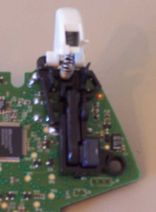
The next step is to remove the plastic trigger assembly that is currently over the left analog stick potentiometers. To do this you first need to disconnect the trigger from it’s potentiometer. This is done by pushing the trigger to the left and the plastic connector that goes to the potentiometer to the right. It should pop out fairly easy. Now we have to remove the trigger from the assembly. To do this just squeeze the trigger together at the end and push it back. It should now look something like this.
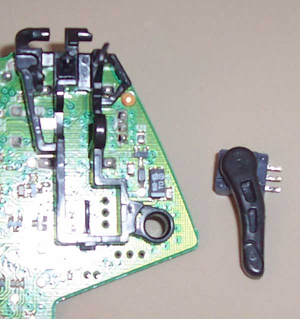
To remove the trigger completely, just slide it to the right.
In order to take the rest of the trigger assembly apart you have to desolder the trigger potentiometer. To desolder, heat up the potentiometer leads one at a time using your soldering iron and use a solder sucker to suck the solder off. There are other ways of desoldering, but that is the way I prefer. After you have the potentiometer desoldered, pull it straight out of the circuit board.
Now that the trigger potentiometer is off of the board, the remaining trigger assembly comes off easily. The left analog stick connections are now exposed.
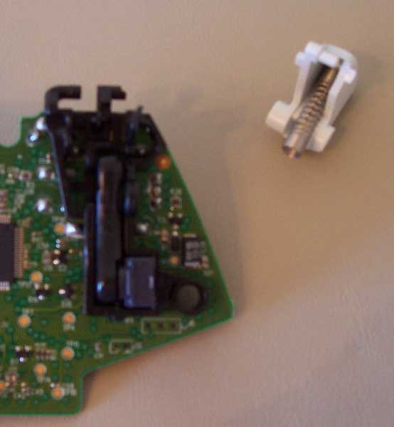
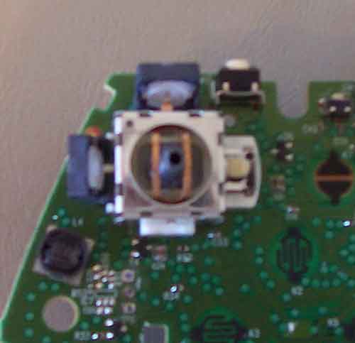
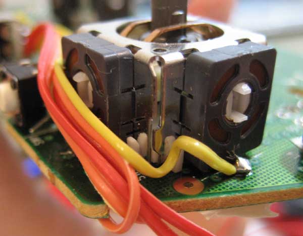
The tiltBoard’s outputs must be connected to the spot that the potentiometer’s outputs are originally connected. However, if both are connected at the same time the voltages from the tiltBoard and potentiometer will fight each other and your controller will get hot (bad). In order to prevent this from happening we have to make sure that the potentiometer output (the middle pin of the potentiometer) does not touch where the tiltBoard’s outputs will be connected. On the wireless board the best way to do that is to desolder the two potentiometers of the left analog stick, take them off the board, bend the middle pins out, and solder them back in. To do this, you must first get the potentiometers out of the analog stick assembly. To do this take a small flathead screwdriver and put it between the potentiometer and the assembly. Now push the screwdriver towards the assembly and the potentiometer will detach from the assembly. A picture of the analog stick with two detached potentiometers is below.
Now you can desolder each potentiometer and remove it from the board. Once it is removed from the board bend the middle pin out and solder it back into place. It should end up looking something like the following picture.

The controller is now all ready for you to solder on your wires. If you are going to be installing a switch, this will be when you do it. Using a DPDT (Double Pole, Double Throw) switch you can wire the controller so you can switch between using the left analog stick for input and the tiltBoard for input. While this switch is handy, it makes the installation more tedious. I will be installing a DPDT switch in this tutorial, but will also go over how to install it without a switch. NOTE: If you do not understand how a DPDT switch works I highly reccomend reading up on it and figuring it out before installing one.
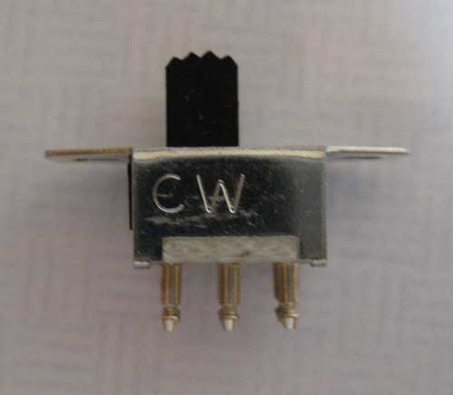
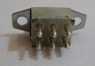
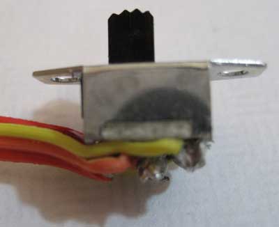
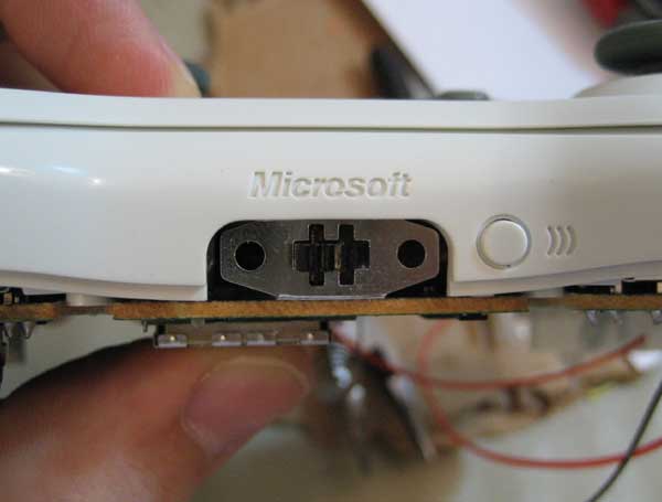
The switch I chose to use looks like the above switch. It is Mouser part # 629-GS1130512. I will be installing it where the top port on the Xbox 360 controller is. I do not use the Xbox 360 Play & Charge Kitso the port is of no use to me. If you want to install your switch in place of the top port you will need to desolder the 7 pins shown below and pull the port off of the controller.
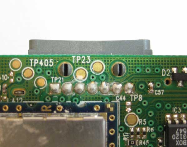
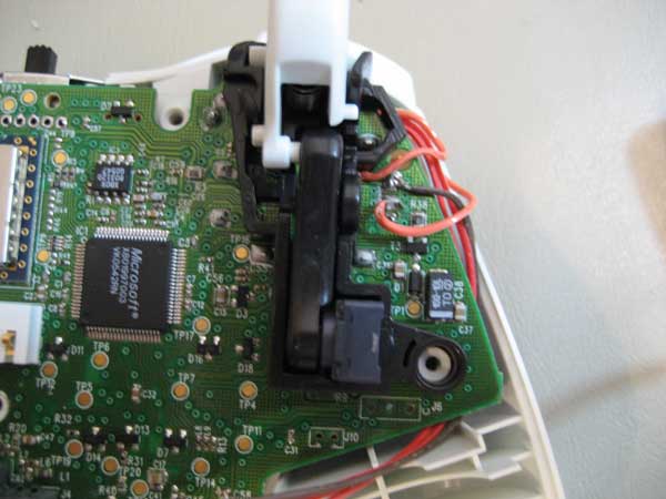
After pulling the port off of the controller, the top of your circuit board will look like the picture below. Please note that the metal bar seen in the picture is the antenna for your wireless controller. If you take this off (and do not replace it) your wireless signal will be greatly diminished.
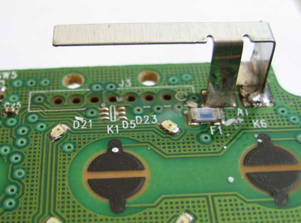
The next step is to position your switch where it is going to go and start cutting and soldering your wires. Before you cut and solder your wires you will want to make sure they are routed in such a way that they will not interfere with any of the controller buttons. In the following steps it is crucial to know how your switch works to ensure you do the wiring correctly. Don’t mix up your X and Y wires! The wires connected to the common leads on your switch should be soldered to where the middle potentiometer pins did go on the circuit board (first picture below) . Another pair should be soldered to the middle pins of the potentiometer (second picture below). The final pair should not be soldered to anything (yet) and just be routed towards the bottom of the controller. This will connect to the XOUT and YOUT of the tiltBoard.
NOTE: If you are not going to be using a switch in your controller, simply solder wires to where the potentiometer center pin used to go (first picture). Those wires will go to the XOUT and YOUT on your tiltBoard. Be sure you know which wire does what! The XOUT should be connected to the left/right and the YOUT should be connected to the up/down.
Once your switch is in place and your wires are soldered, put the trigger assembly back on the board. First put the plastic piece back on, re-solder in the potentiometer, and finally connect the trigger to the trigger assembly. It is just the reverse of what you did earlier.
Good news– The hard part is over! All that is left is adding the GND, V+ and VREF wires to the board and soldering five wires to the tiltBoard.
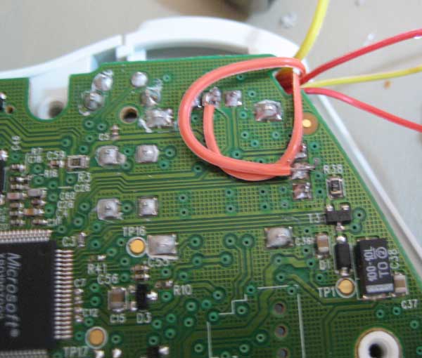
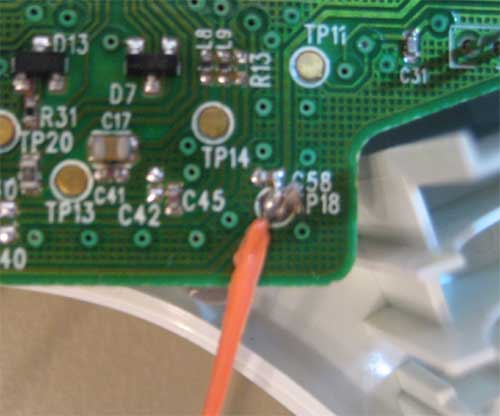
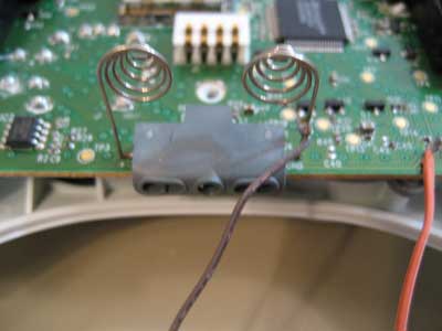
The VREF wire is soldered to the top pin on the Y-axis potentiometer. It is the brown wire in the first picture below. The V+ wire is soldered to “TP18” and is on the lower right hand part of the board. It is the orange wire in the second picture. This point outputs a little over three volts. This is actually higher than the battery voltage going into the controller and is a good place to hook into because as your batteries go low, your tiltBoard should (untested) work the entire time your controller does. Unfortunately, this point still supplies a voltage identical to that of the batteries when the controller is off. This means that the tiltBoard will be drawing current (draining the batteries) even if your controller is off. The tiltBoard draws less than 10mA, but I would still disconnect my battery when not using it. If anyone finds a good place to solder to (2.7V or above) that does not supply voltage when the controller is off, please make a posting in the forums or e-mail me. The ground wire can be soldered directly to the ground battery spring (picture 3 below).
Now your controller should be completely wired. It is time to put the rumble motors back in and if you haven’t done so already, the bottom gray piece. Remember that the smaller rumble motor goes on the left side. You should have something like the picture below.
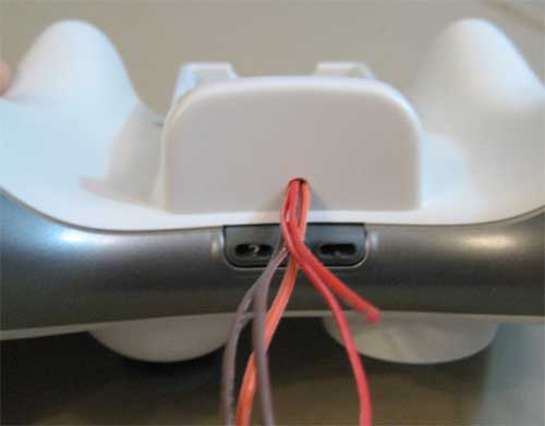
Now put the bottom of the controller case on and route all of the wires out the back of it through the battery slot. Put all of your screws back in and tighten everything down. Test all of your buttons to make sure that they feel right. If it doesn’t feel right, a wire or something else is probably stopping the board from laying correctly. Take it apart, re-situate it and keep trying until all your buttons feel right.

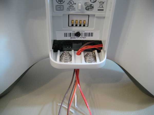
Now it is time to drill a hole in the bottom of the controller. The hole needs to be big enough for your wires to fit through. When drilling the hole make sure it is in the lower center of the battery pack. If the hole is too high it will interfere with the batteries.
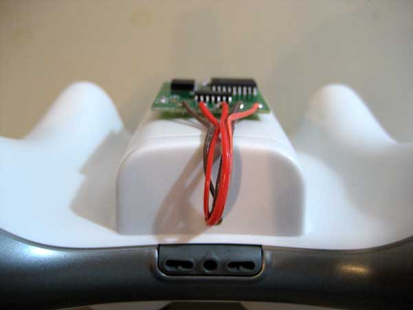
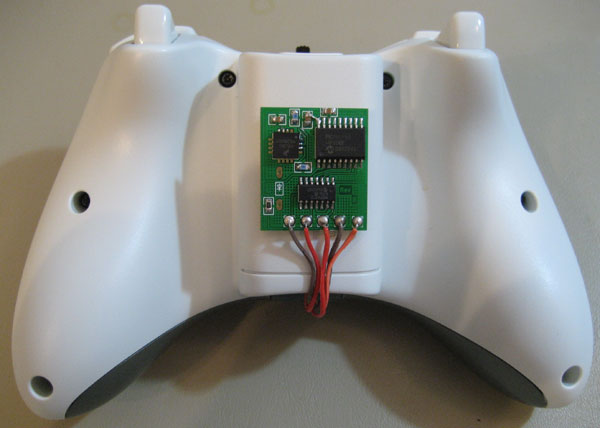
Now it is time to get out your tiltBoard and situate it on the controller where you want it (preferably center of battery holder). Once it is situated cut and solder all of your wires to it. You will probably want to do your soldering off of the actual controller so you don’t melt any part of the back of your case. The pin numbering goes from left to right. 1) VREF, 2) XOUT, 3) YOUT, 4) GND, and 5) V+.
Once you have the tiltBoard soldered, just peel the foam tape backing off of the back and stick it firmly onto your controller. Your done!
If you cannot get your tiltBoard to work for whatever reason, please ask in the forums. This gives other users a chance to help you instead of just me, and having the information publicly available may help someone else who is having the same problem.
I see where some of your first profits went to. 😉 Nice camera!
Are the boards supposed to have a sticky back to them? Mine does not seem to have a back that will peel. Maybe I am missing something.
would i be able to send u my controller to mod cuase the mods sweet. nice work
maybe pictures of exactly where you solder all the wires to would be great. to hard to figure out , nice work but can tell you are an engineer because the documentation is horrid.
I despise making documentation. 🙂
That said, I have a picture of everyplace you need to solder a wire, so I am unsure what you are asking.
i think we “dumber” people need like a paint by numbers tutorial for this install
it would make it more easy
I didn’t think that it was hard to understand if you know how a switch works. Adam showed exactly where every wire needs to go on the board.
Can you put scheme of the instalation?
can you do it for mr and i will pay you for the labor as well
so like when’s this controller being produced by talismoon? i’m really eager to get myself this device
Would the mod chip fit under the battery somehow? coz i seen pix of dat.
is there a chance to use a ps3 controller
can you share the project of the integrate circuit or is reserved?
do u accept others xbox parts from people who wants u to do it for them. and mod them and send it back or do u mod for u only and not for others