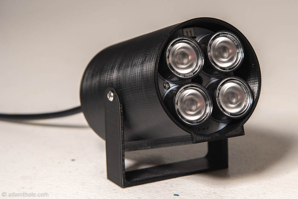
This is part 2 of the Smart Home Magic Wand series which focuses on the WiFi streaming IR camera / emitter. This is what will emit IR light out to the wand and read the reflected IR light back from the tip of the wand. Part 1 gives more background on the project and discusses the wand in depth.
This IR Camera system combines a Raspberry Pi Zero W, a Pi NoIR Camera V2, an IR filter, IR lights, and a 3D printed case to create a WiFi streaming IR camera that will be used as the input to the software that will be discussed in Part 3.
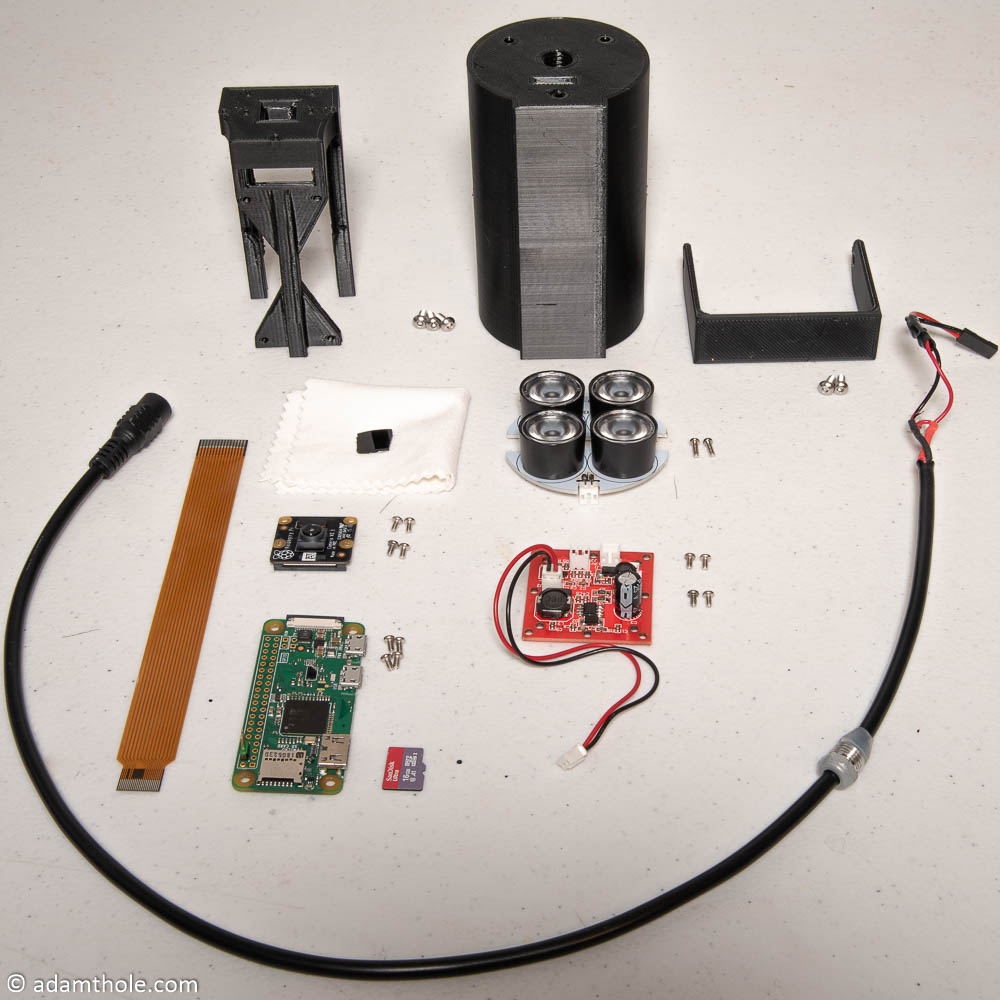
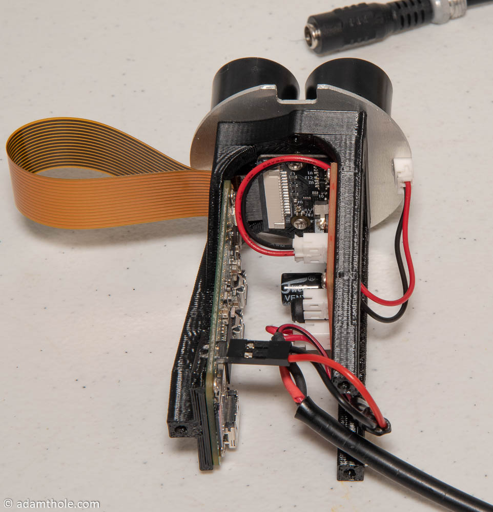
The picture above shows all pieces used to create the streaming IR camera system. They are as follows:
- Raspberry Pi Zero W
- Raspberry Pi NoIR Camera V2
- Raspberry Pi Zero V1.3 Camera Cable
- High Power LED IR Illuminator (disassembled)
- IR LED Board
- IR Power Board
- Power Cable
- 5V BEC
- IR Filter (optional)
- 12 M2 x 4 mm screws
- 2 M2 x 6 mm screws
- 5 M3 x 8 mm screws
- 3D Printed Case (3 parts)
- Micro SD Card
- 12 V Power Supply
Many of the parts shown in the picture above are from a disassembled High Power LED IR Illuminator. In this project I reuse the cord, the power board (pictured red above), and the IR LED board. If you buy the linked one, it is fairly easy to take apart and separate the components. In order to use one source of power for the IR lights and the Pi, I used a 5V BEC to convert the 12V input to 5V for the Pi. In the picture above the BEC is already added to the wire and is heat shrink wrapped near the end of the wire. The input to the BEC is the 12V from the IR Illuminator, and the output is wired to a standard 2-pin 0.1 header for plugging into the Pi Zero. The original connector is also coming out of the connector to supply the red power board with 12V.
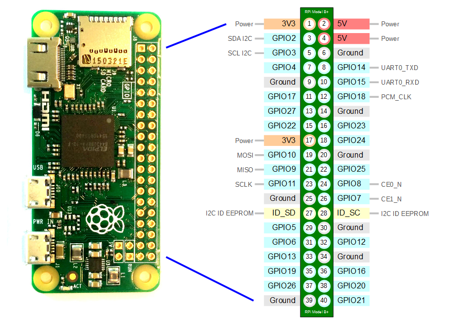
If your Pi Zero W does not come with a header, you will need to add a 2-pin header to the power pins in order to power the Pi Zero W. The recommended power pins are pins 4 and 6 as shown below. For more Pi pinout information check out pinout.xyz.
The STL files for the 3D printed case are available here. There are three parts: Electronics Holder, Camera Shell, and Base. They need to be printed in something that can withstand high temperatures, as the IR LED board gets hot. PLA will not work. I used PETG without any problems. There is threading as part of the camera shell, so a higher resolution would be best. I printed at 0.1 mm layer resolution.
Raspbian Setup
On the SD card I used the most recent copy of Raspbian Stretch Lite. Once you write the image to your SD card (I used Etcher ) you will need to make an empty file called “ssh” in order to be able to ssh into your Pi. In order for the Pi Zero W to connect to your WiFi network you will also need to create a file called “wpa_supplicant.conf” with the following text:
country=US
ctrl_interface=DIR=/var/run/wpa_supplicant GROUP=netdev
update_config=1

network={
    ssid="YOUR SSID"
    scan_ssid=1
    psk="YOUR PASSWORD"
    key_mgmt=WPA-PSK
}
You will need to change the country, ssid, and psk (password) to match the settings of your WiFi network.
Once this is complete, eject the micro SD card, put it into your Pi Zero and power it up. Once it is powered up, find it’s IP address (using your router, Fing, etc.). You will need to have a static IP address on the Pi so we always know where to find it. I use a DHCP address reservation feature in my router, but you can also use a static IP configured on the Pi if you prefer.
Once your Pi is configured with a static IP, SSH into it. To perform the video streaming we will use mjpg-streamer, specifically the variant by jacksonliam. You can find it on GitHub here.
Run the following commands on your Pi to perform the initial updates:
sudo apt-get update
sudo apt-get -y upgrade
sudo rpi-update
sudo reboot
After the Pi reboots, SSH back into is and run “sudo raspi-config”. This will open the raspi-config menu. Arrow down to “Interfacing Options” and enable the camera. Once the camera is enabled press the right arrow to finish, and select yes on the menu option to reboot.
After the Pi reboots, SSH into it and run the following commands to install mjpg-streamer:
sudo apt-get -y install cmake libjpeg8-dev
sudo apt-get -y install git

cd ~
git clone https://github.com/jacksonliam/mjpg-streamer.git

cd mjpg-streamer/mjpg-streamer-experimental
make
sudo make install
After running those commands, mjpg-streamer should be installed on your Pi. To test it, run the following command:
./mjpg_streamer -i "./input_uvc.so -r 640x480 -f 41 -rot 0" -o "./output_http.so"
This will start streaming from your camera at a resolution (-r) of 640×480, at a frame rate (-f) of 41 fps, and rotating (-rot) the image 0 degrees. In order to view the stream type the following URL into a web browser:
http://192.168.1.107:8080/?action=stream
Note that the IP address of my Pi Zero W is 192.168.1.107. You will need to change that address to match the address of the Pi you are using.
If you are successful, you should see something like the following:
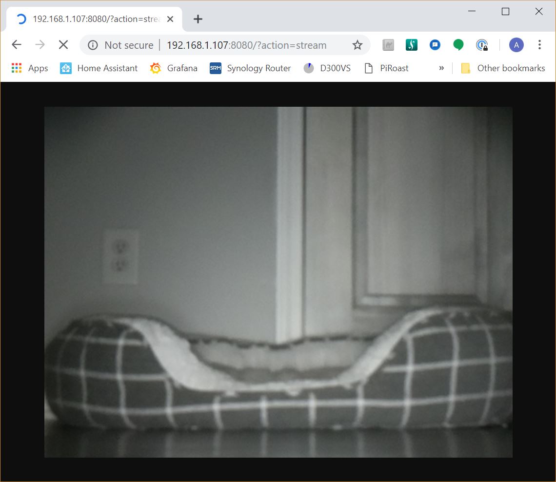
Note that in my test image I already have the IR filter installed, which is why it looks black and white. If you haven’t installed the IR filter yet you will see a color image.
Before moving on to the next step I wanted to state the significance of setting the frame rate to 41 fps. This is done to force the hardware to use a partial FOV (field of view) so the camera only uses part of the sensor. It is the equivalent of zooming in on the image the camera sees. If the fps is under 40, the FOV will be the entire sensor, a much wider area. This matters for our purposes because the wand motion will be harder to track in the wider view unless you (the wand) are closer to the camera. For my purposes the partial FOV worked best, but you should play around with it and see what works best for your setup. If you do use the full FOV by setting the frame rate lower, you will have partial blockage due to the IR light lenses. The higher the fps the more processing power that will be needed for the software portion (part 3) of the project. You can set the fps as high as 90 if you prefer. Only one of the Pi Zeros I tested was able to maintain 90 fps constantly without shutting down, likely due to overheating. That is the main reason I chose 41 fps here instead of 90 fps. More information about Pi camera resolutions, frame rates, and FOV can be found here.
Now that we have the Pi up and the streaming software installed, we need to make it so the Pi automatically starts the streaming software on boot. To do this we will setup a service for systemd. Send the following commands to the Pi via SSH:
cd /etc/systemd/system
sudo nano mjpgstreamer.service
This will open up a text editor that is bank. Put in the following text:
[Unit]
Description=A server for streaming Motion-JPEG from a video capture device
After=network.target

[Service]
User=root
ExecStart=/home/pi/mjpg-streamer/mjpg-streamer-experimental/mjpg_streamer -i "/home/pi/mjpg-streamer/mjpg-streamer-experimental/input_uvc.so -r 640x480 -f 41  -rot 0" -o "/home/pi/mjpg-streamer/mjpg-streamer-experimental/output_http.so"

[Install]
WantedBy=multi-user.target
Press ctrl-X to stop editing, and Y to save the file. You just created a service file that can be used to automatically start the mjpg-streamer automatically on boot using systemd. Next we need to enable this service:
sudo systemctl --system daemon-reload
sudo systemctl enable mjpgstreamer
sudo systemctl start mjpgstreamer
With those commands, your Pi should automatically start mjpg-streamer on boot. Go ahead and reboot (sudo reboot) to give it a try.
Hardware Assembly
Now that your Pi Zero is fully configured and functional, it is time to start assembling the camera system.
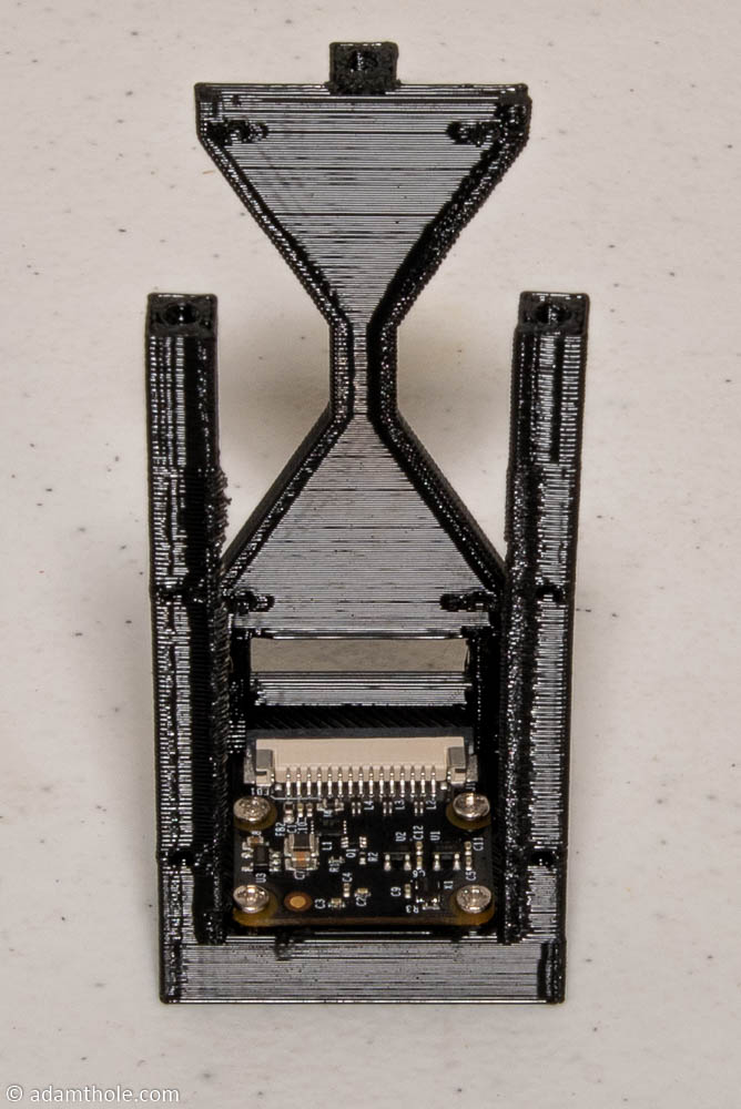
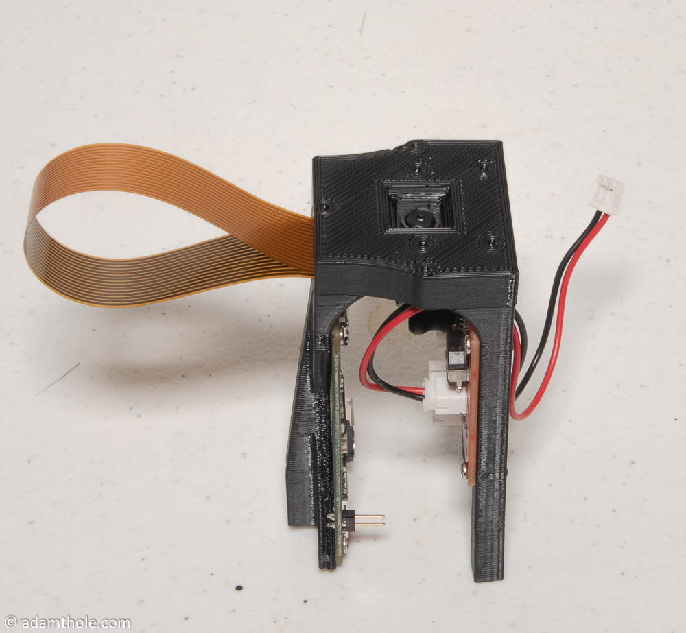
Step 1: Install camera into electronics holder with 4 M2 x 4 mm screws.
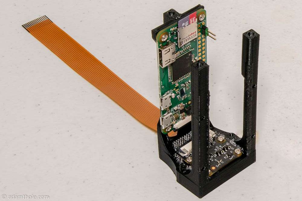
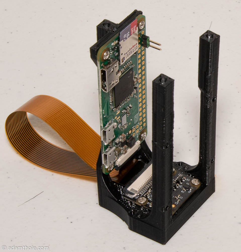
Step 2: Insert the camera cable and micro SD card into the Pi Zero, then screw the Pi Zero W to the electronics holder with 4 M2 x 4 mm screws. Be sure the Pi camera cable goes through the hole in the back of the electronics holder.
Step 3: Connect the Pi camera cable to the Pi camera as shown.
Step 4: Install the power board from the IR illuminator onto the electronics holder using 4 M2 x 4 mm screws.
Step 5: (optional) The electronics holder has a built in slot for an IR filter that will only allow IR light to pass through. This will help with false positives when tracking the wand. I used a cheap glass IR filter that I scored with a knife and broke into roughly the size needed to match the hole in the electronics holder.
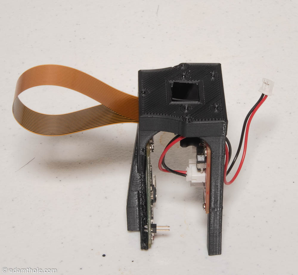
Step 6: Install IR LED board on top of electronics holder using 2 M2 x 6 mm screws. Note that the IR LED board holds the IR filter glass into position.
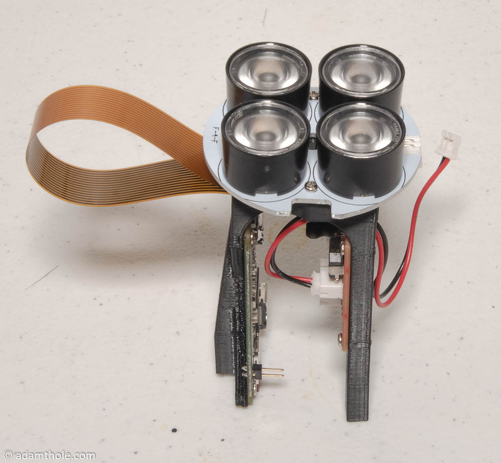
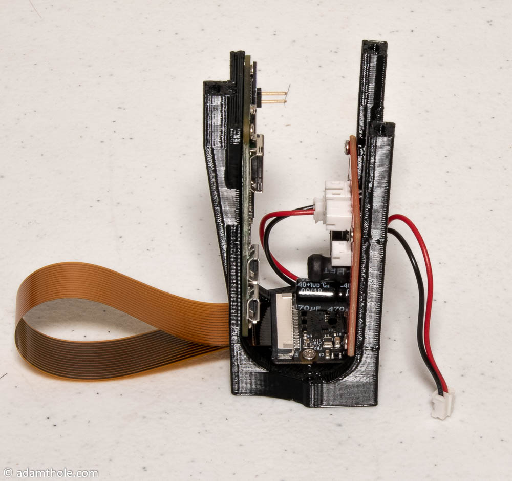
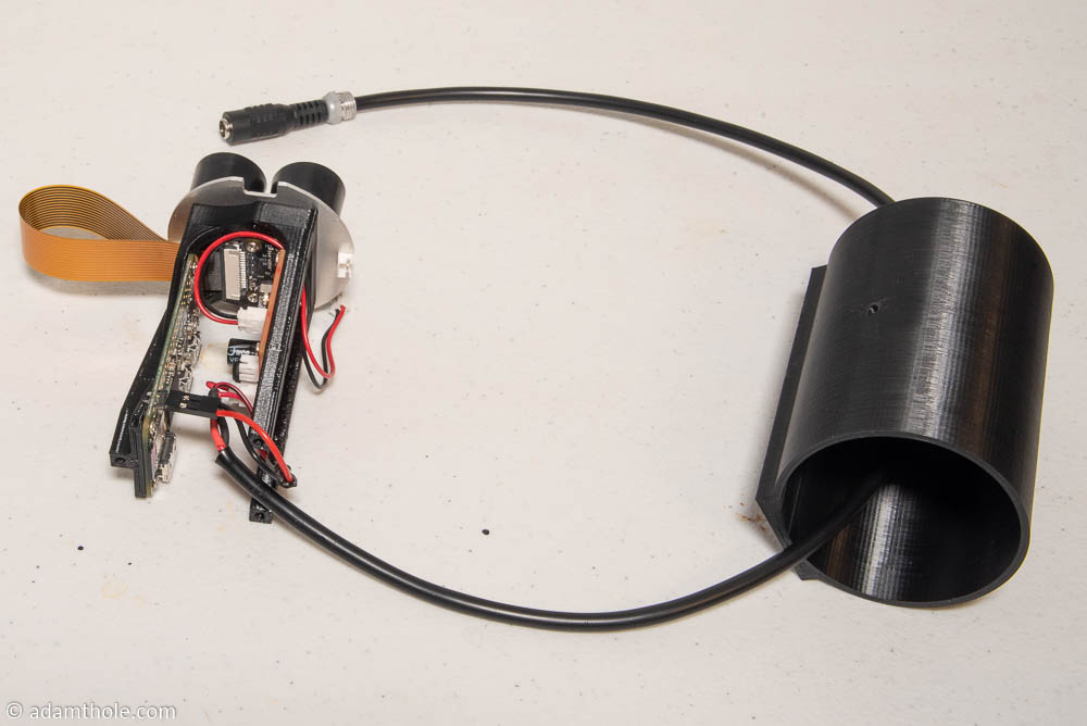
Step 7: Route the power cable through the back of the 3D printed camera shell and connect power to the Pi and IR power board.
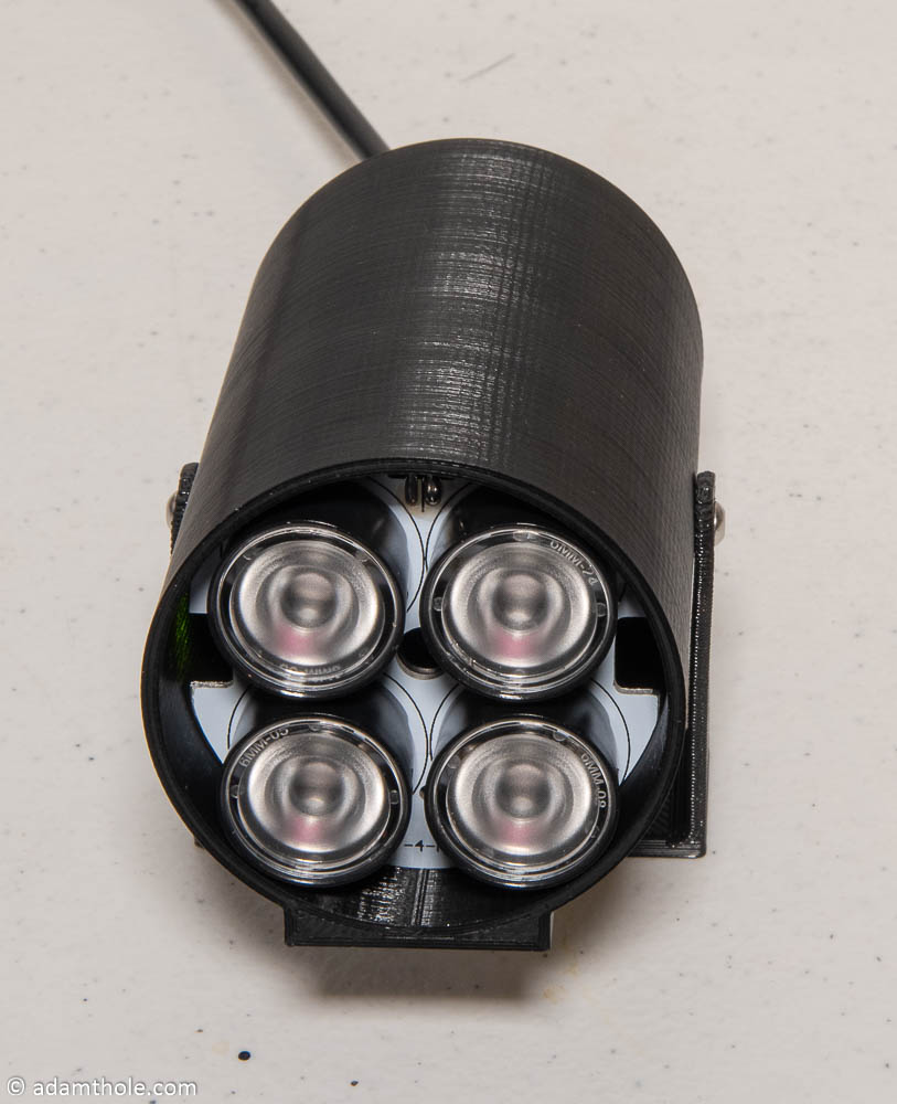
Step 8: Connect the power cable from the IR Power board to the IR LED board as seen near the top of the picture below.
Step 9: Now all of the wiring is connected and it is time to put the electronics holder inside the camera shell. Slowly push the electronics assembly into the shell being careful to help the power cord stay out of the way. Eventually it should fit entirely inside the shell with the micro SD card hanging slightly out the back. The micro SD card helps with getting everything aligned correctly.
Step 10: Once everything is aligned, use 3 M3 x 8 mm screws to secure the electronics assembly inside the camera shell.
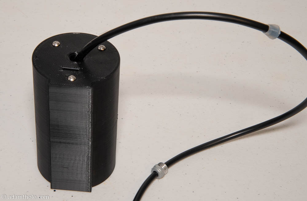
Step 11: Carefully move the rubber grommet from the power cord inside of the hole in the back of the camera shell. Make sure power cord is in a neutral position so minimal strain is on the power connectors inside the shell.
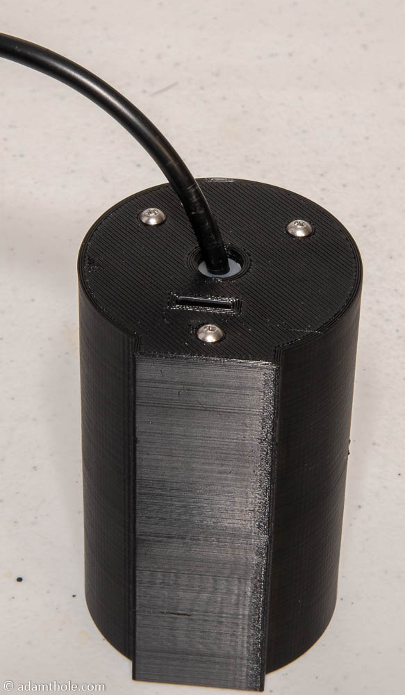
Step 12: Screw the power cord nut into the back of the camera shell. This should keep the power cord firmly in place and prevent unnecessary stress on the power cables.
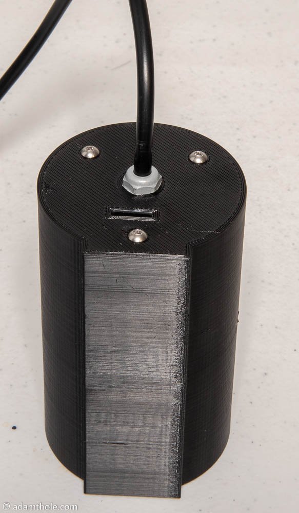
Step 13: Screw the base plate onto the camera shell using 2 M3 x 8 mm screws.
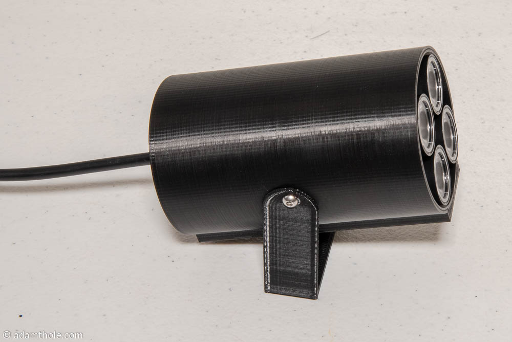

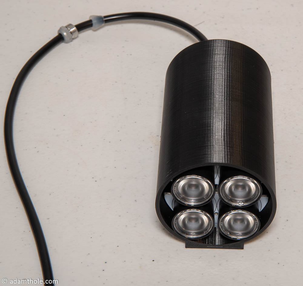
That’s it! Your WiFi streaming IR camera is complete! Power it up and make sure it all works. In part 3 of this series we will use software to tie everything together.
Hi Adam – I’m successful with the instructions down to the part to test the camera with:
./mjpg_streamer -i “./input_uvc.so -r 640×480 -f 41 -rot 0” -o “./output_http.so”
I get the error:
MJPG Streamer Version: git rev: 501f6362c5afddcfb41055f97ae484252c85c912
i: Using V4L2 device.: /dev/video0
i: Desired Resolution: 640 x 480
i: Frames Per Second.: 41
i: Format…………: JPEG
i: TV-Norm………..: DEFAULT
ERROR opening V4L interface: No such file or directory
i: init_VideoIn failed
I have searched a few forums and get a few solutions like this:
You need to load the bcm2835 Video4Linux driver module.
Load it with: modprobe bcm2835-v4l2
But this hasn’t worked for me.
Any suggestions?
Thanks!
Started from the beginning and got the camera working…
That’s great Andy, I’m glad you got it working! Let me know how the rest goes!
Not sure this is your solution, but I had the same error. I hate to admit it, but I had the cable ribbon for the camera in backwards. Switched it around and now it works perfectly. If you have a pi camera (i have a noir and a pi 4)…the blue part of the ribbon cable should be facing your ethernet port.
Hi Adam –
I am in the same boat. Everything goes great until the test command – ./mjpg_streamer -i “./input_uvc.so -r 640×480 -f 41 -rot 0” -o “./output_http.so”
I get the same V4L error:
MJPG Streamer Version: git rev: 501f6362c5afddcfb41055f97ae484252c85c912
i: Using V4L2 device.: /dev/video0
i: Desired Resolution: 640 x 480
i: Frames Per Second.: 41
i: Format…………: JPEG
i: TV-Norm………..: DEFAULT
ERROR opening V4L interface: No such file or directory
i: init_VideoIn failed
I have rebuilt everything twice (all the way back to using Etcher to reformat and reload the card) and I get the same error every time. Am I missing a step or some other program I am not aware of?
Can you refresh your line to the 5V BEC? I am trying to figure out how much each camera costs to build.
The link to the 5v BEC is broken. Any alternative?
btw, I was able to use an iflight micro bec purchased here:
https://www.racedayquads.com/products/iflight-3-6s-micro-5v-bec
They’re currently sold out
Sorry for the late reply, almost any 5V BEC should do the trick. They are a very common hobby store item. Glad you were able to find another!
search the description on amazon…should come up. I found one.
I am trying to duplicate this project for a trunk-or-treat. I have all of the components on hand except the IR illuminator. Is this absolutely necessary?
You will need an IR illuminator of some sort. Without it the IR camera will not be able to pick up the tip of the wand. You don’t need the exact one I used.
Would it be possible to purchase a WiFi steaming IR camera and have the software work with that or do you have to build this one?
Grant – Yes, this would be possible, but it would need to be a camera that has an interface that OpenCV can take as an input.
I’m running into errors once I run Make at about 31%…any ideas? I’d guess it’s a syntax error of some kind in the “input_opencv.cpp” file, but others seem to be installing without any issues. Thanks for any insight you might provide.
[ 31% ]Building CXX object plugins/input_opencv/CMakeFiles/input_opencv.dir/input_opencv.cpp.o
/home/pi/mjpg-streamer/mjpg-streamer-experimental/plugins/input_opencv/input_opencv.cpp:86:5: warning: invalid suffix on literal; C++11 requires a space between literal and string macro [-Wliteral-suffix]
” Help for input plugin..: “INPUT_PLUGIN_NAME”\n” \
thedood – I’m afraid I’m not an expert when it comes to compiling OpenCV. I would recommend asking Adrian over at https://www.pyimagesearch.com/ if you are still having issues. That is where I go when I want to compile a new version.
Any chance you could share the 3D printed parts in an alternative file format? I’d like to customize the parts for different mounting purposes. Parasolid files play well with OnShape – but STEP or SLDPRT would also work.
And thanks for the awesome posts – the whole family is looking forward to having this up and running in our house!
Jacob – I can do that. I added it to the GitHub: https://github.com/adamthole/PyPotter/tree/master/Mechanical Let me know how it goes!
Thank you!
Hi Adam-
Thanks for putting this tutorial together. The kids and i are going to be walking thru this soon. collecting all of the parts now.
Quick question on the power situation…
You are powering both the Pi and the IR illuminator off of the same power input (the power cord from the IR LEDs) it looks like. so you cut the power cord to disassemble the IR, then split the power. 1 thru the BEC to the Pi, the other straight to the original IR LED power board. right?
just want to make sure i have the power setup correctly. just tough to tell how you have some of the power cords in the pictures.
thanks!
Hi Mark,
You are exactly correct on the power setup! I hope you and the kids enjoy, let me know how it goes!
Question for anyone who has made these before. I am creating it right now and it is going ok, but when I move this from my office to my house (different wifi), what will I need to do to get it to connect to my home wifi? Hoping I dont have to start all over with the .conf file again. I am new to Raspberry pi, so explaining it in simple terms is appreciated.
Hi Adam,
Thank you for the guide I got everything up and running and tracking great. The only issue I’m having is after pointing the wand initially or “finishing” a spell it takes 15+ seconds for it to end that “spell” often ending in the spell not working because there is now a big blob from where I’ve been holding the wand a still as possible.
Hey Mike,
Sorry to hear about the trouble. At what FPS is openCV processing your data? It may be too low and is causing a long time to trigger then end of movement.
Adam,
I just recently took my first trip to universal and found this after I purchased my wand. I purchased the https://www.amazon.com/gp/product/B01D73XM24 but i’m not picking up an IR reflection in my camera…any ideas?
Hey Jonathan,
Most cameras specifically filter out IR light. You will need to use a specific IR camera (or at least one without an IR filter) in order to see the reflection.
ROFL…thanks. I don’t know how long it would have taken me to figure out I had swapped my cameras when I was building this and my OctoPrint at the same time!
Hey Adam! I’m having trouble getting the camera to be recognized by the Pi…the vcgencmd get_camera command returns supported=0 detected=0 when I follow your steps. While trying to follow this specific problem, I have checked the camera/I2C settings, tried tracking down/creating a missing dt-blob.bin file, checking for missing lines of code in /boot/config.txt…nothing I do seems to even get the Pi to admit that it can support a camera, much less recognize mine. Any ideas? Would love to get this working for my girlfriend so she can turn on the Christmas tree 🙂 Thank you!
cannot get it past this stage PI3B+ latest rasping OS lite
$ sudo apt-get -y install cmake libjpeg8-dev
Reading package lists… Done
Building dependency tree… Done
Reading state information… Done
Package libjpeg8-dev is not available, but is referred to by another package.
This may mean that the package is missing, has been obsoleted, or
is only available from another source
However the following packages replace it:
libjpeg9-dev libjpeg62-turbo-dev
mat,
I changed the 8 to a 9 in the command “$ sudo apt-get -y install cmake libjpeg8-dev” and was able to move past that.
Still trying to get some video to display though. 🙁
This looks like a fantastic project. I started printing the parts today and waiting on my order of other parts to come in. In the meantime, I have a Pi 4 set up with all of the code and tested a standard Pi camera — it works!
I plan on using a Pi 4 for this project and was just curious if you made a different STL or housing to include changing to another Pi? I saw on Part 3 you are now using a Pi 3 b.
Thanks for all the work on this.. awesome stuff!