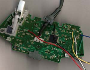
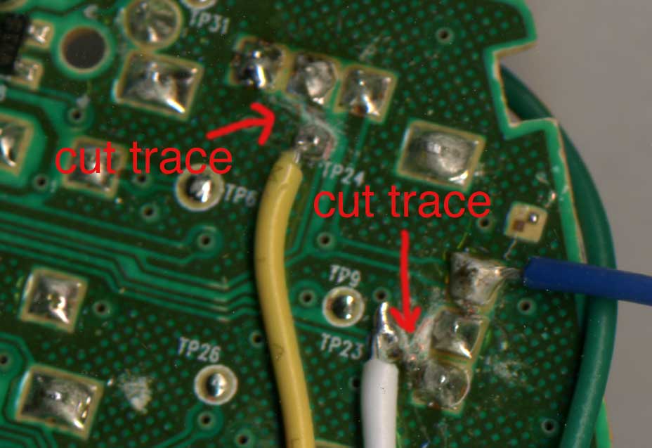
Once I took the controller apart and learned about it (see phase one) it was time to solder wires to the points I needed and to cut a couple traces. First I needed power so I soldered a black wire to ground and a red wire to the +5V from the USB. The blue wire gets the 1.61 V maximum voltage from the potentiometer. I needed a wire to each of the center potentiometer pins for the Y and X axes. I used a white wire for the Y axis and a yellow wire for the X axis. Because I would be outputting a voltage and the potentiometer would be outputting a voltage it was necessary to cut the trace from the center potentiometer pin and solder my wires further down on the trace. If I did not do this I would be getting an input voltage from the potentiometer on my output pins on my microcontroller and that would not be good. I ended up soldering to test points TP23 and TP24. Below is a picture of the controller board with all of the wires soldered and both traces cut. The green wire was for switching between using the analog stick and the controller’s tilt for input which I later decided not to do (with this version anyway) so the green wire should be ignored.
After doing more research I found out that I only need a two-axis accelerometer to measure the left/right and up/down tilt. The tilt is determined by measuring the force of gravity on the axis. Both axes start out perpendicular to gravity and no force from gravity is felt. As you tilt the accelerometer gravity starts acting on it more and more. When it is tilted 90 degrees so the axis is parallel to gravity it will be experiencing the full force of gravity. When it is in between perpendicular and parallel it will experience varying amounts of force. You can figure out exactly what degree you are tilted by taking the arcsine of the output. More detailed and full information is available in this document by Freescale. For this project’s accelerometer I decided to go with the MMA6260Q. It is a two-axis accelerometer that does everything I need it to do and is priced reasonably.
For my DAC (Digital-to-Analog Converter) I decided to go with the MCP4922. This is a two output DAC card manufactured by Microchip. It uses an SPI interface, so it is pretty easy to talk to with a microcontroller. For the brains I went with my standard PIC 16F88. I have several of these microcontrollers on hand and know the ins and outs of them very well. I have used the 16F88 in most of my past projects. When you just use one chip for all of your projects it makes things much easier because it is easier to remember what the different registers of that chip are and what they do.
The code for this project isn’t too complicated for the most part and works in three phases. In the first phase the microcontroller reads the analog voltage output to it by the accelerometer. Since we are dealing with two axes we read in two voltages and store those values. The second phase of the program is the most complicated and is where the degree of tilt is determined. I used a look up table for this process. Once the degree of tilt is determined that number needs to be converted to a value between 0 and 0xFFF (for my DAC) where 0 will be output to your controller as full tilt one direction and 0xFFF will be output as full tilt in the other direction. My look up table is sent the analog voltage value from the accelerometer and returns the degree of tilt from -90 to 90 degrees. I set my full tilt value for the x-axis (left/right) to be 60 degrees. That means that 60 degrees of tilt left is equivalent to pushing the analog stick fully left and 60 degrees of tilt to the right is equivalent to pushing the analog stick fully to the right. For the y-axis (up/down) I set the full tilt value to be 45 degrees. This again means that 45 degrees of tilt forward is the equivalent of pushing the analog stick completely up and tilting the controller 45 degrees back is the equivalent of pushing the analog stick completely back. I chose the smaller full tilt value for the Y-axis because you can only tilt the controller forward or backward a small amount comfortably and I thought that 60 degrees was to far. I did all of my programming in C. I used SourceBoost as my IDE and I highly recommend it.
Over the weekend I was suprisingly successful with this project. My first task was to interface to the DAC and it worked without a problem. After the DAC I did the dreaded job of making the accelerometer board and soldering the QFN package. For those not familiar with QFN packages, they have no leads. This means that you basically have nothing to solder to except a tiny shred of metal that is flat against the case. Suprisingly my soldering job to the QFN package was successful and the accelerometer worked without a problem. After that I worked on my program that tied everything together and had a working product on Monday. My next job is to make the tiny circuit board that will be mounted to the back of the 360 controller and get a video up of this working.
Your guide it is helping me finish a project close to this one, there is a few things your guide leaves out, if you could put a more detailed one out, I will be finishing the same project. I live in Korea, so i am going to see if I can find an accelerometer downtown, shipping from the states is expensive.
I will warn you i have be self teaching myself how to work on projects like this, but this is this idea is completing my idea, thank you very much!
could you be a little more spacific about the details, IE, a electronic diagram, and maybe a little programming and flashing tutorial for the unexperienced.
i would also want to know when you’re planning to get the single chips on sale. i would at least buy a dozen of them for my friends.
Hi,
I found your blog via google by accident and have to admit that youve a really interesting blog 🙂
Just saved your feed in my reader, have a nice day 🙂
But why? What use does a motion controll controller have in a game where thats not supported!