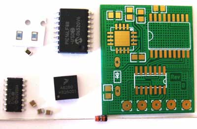
The tiltBoard kit is a version of the tiltBoard that comes with all of the necessary parts to make the tiltBoard, but is not pre-assembled. The kit includes the parts seen in the above picture.
The tiltBoard kit can make either the 3V or the 5V version of the board. If you want the 5V version simply solder in the zener diode (Z1). If you want the 3V version of the tiltBoard, do not solder in the zener diode (Z1). That is the only difference between the two versions.
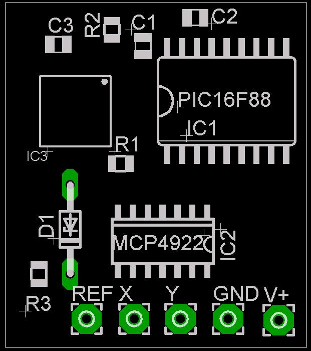
Above is the silkscreen of the tiltBoard with part names and numbers added. Solder the appropriate component to the appropriate spot on the board.
- IC1 – PIC16LF88
- IC2 – MCP4922
- IC3 – MMA6260
- R1 – 1K ohm
- R2 – 1K ohm
- R3 – 100 ohm
- C1 – 0.1 uF
- C2 – o.1 uF
- C3 – 0.1 uF
- D1 – 3.3V Zener Diode
The hardest part to solder in this kit is going to be the accelerometer (IC3). This comes in a QFN package and can be tricky to solder. I usually solder it first just to get it out of the way. Make sure the dot on the accelerometer matches up with the dot on the silkscreen of the board. Also make sure IC1, IC2, and D1 (if used) are aligned correctly on the board before soldering them.
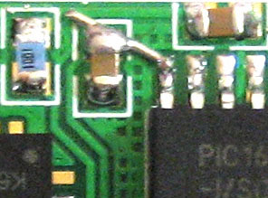
Board Error – Jumper Needed – All Rev B Boards
When I converted my PCB files into the format needed for production one trace was left off, so a jumper will need to connect the two points together. The jumper should connect the top of C1 to pin 18 of the PIC. The jumper is seen in the picture beleow and is easy to make with a small piece of the diode lead. Sorry for the inconvenience! This error only affects “Rev B” boards.
Greetings!
I just want to commend you on this excellent innovation. It is indeed very creative. Quick question:
Will this kit work for wireless controllers as well?
to the comment above yes it does work for wireless controllers the wireless controls = 3V, wired = 5V
Did you solder down the thermal pad on the QFN? If so, is there vias for this? Any tips on how to solder the thermal pad?
Eddie, You do not need to solder down the center pad on the QFN. I assume that is the thermal pad? When I do the QFN’s I actually only solder the 4 pins that I need. The process I have had the most luck for soldering the QFN’s is as follows:
Apply solder to one of the pads on the PCB. Keep this solder hot and slide the QFN into position. After the QFN is in place, solder the other necessary pins by heating up the pad and the lead end of the QFN. When I take the soldering iron off of the pad, I go straight up and against the QFN. This causes the solder that follows the iron when you remove it to be on the end of the QFN lead.
Hope that helps!
-Adam
Yes, the center pad is a thermal pad. It is used for thermal heat dissipation. Thanks for the information. This is going to be my first time soldering a QFN. I appreciate your advice. Thanks
-Eddie
Just got my kit today. I’ll hopefully have it all put together and ready to test tonight. Can’t wait.
wow
this is complete and utter genius
how much the multi axis tilt thingie is?
thnx
This man is a genius!!!
Just found your site and this pretty cool mod.
I was wondering how you were getting those pcb created. I’ve been looking at random projects and I always end up using the crappy RadioShack multi-purpose board and it would be great to get some custom ones made.
Let me know. (i might get a kit from you too, as long as the angle can be adjusted, so that it does front back, left right)
Thanks
this is a brilliant invention and will add a bit more spice to the console, but it only leaves me thinking that with the current consoles on offer (nintedo wii and playstation 3) both have this feature as stock, it makes me wonder why microsoft didnt think of this.
its excelent que se chinge el pinche nintendo wii y su pinche palanca toda fea y el pinche playstation3
Will the controller still have rublme funtions?
and will rumbel and tilt word togetter at the same time?