Xbox 360 Tilt Controller – Finished!

tiltbackside.jpg

The Xbox 360 tilt controller is finished! I got rid of my breadboard mess, switched to mostly surface mount components and put everything onto a circuit board. It sure is easier to play games without wires hanging everywhere! I will be releasing a video of the finished version of this soon, but nothing has changed game play wise since the phase two video (below). You can find all of the details about this project in the phase two post also.

Let me know what you think about this and whether or not I should make a wireless version. Also, I would like my projects to start becoming self sufficient, so if you are interested in buying a 360 tilt controller or maybe just a soldered circuit board, let me know. You can either leave a comment or send me an e-mail at: [email protected]

Xbox 360 Tilt Controller – Phase Two – Video

Here is the video of the tilt controller in action. I played Full Auto and Marble Blast Ultra for the Xbox 360, Crimson Skies for the Xbox (on the 360), and Goldeneye 007 for the N64 on a Windows laptop. I wish I could have gotten better quality on the Xbox titles, but I only had a CRT to play the games on.

When I play Goldeneye 007 on the laptop I am using the keyboard to shoot because when I shot that video I didn’t have the controller guts inside the controller yet so none of the buttons worked.

Enjoy!

Xbox 360 Tilt Controller – Phase Two

360wirescloseup.jpg

Once I took the controller apart and learned about it (see phase one) it was time to solder wires to the points I needed and to cut a couple traces. First I needed power so I soldered a black wire to ground and a red wire to the +5V from the USB. The blue wire gets the 1.61 V maximum voltage from the potentiometer. I needed a wire to each of the center potentiometer pins for the Y and X axes. I used a white wire for the Y axis and a yellow wire for the X axis. Because I would be outputting a voltage and the potentiometer would be outputting a voltage it was necessary to cut the trace from the center potentiometer pin and solder my wires further down on the trace. If I did not do this I would be getting an input voltage from the potentiometer on my output pins on my microcontroller and that would not be good. I ended up soldering to test points TP23 and TP24. Below is a picture of the controller board with all of the wires soldered and both traces cut. The green wire was for switching between using the analog stick and the controller’s tilt for input which I later decided not to do (with this version anyway) so the green wire should be ignored.

cuttraces360close.jpg
After doing more research I found out that I only need a two-axis accelerometer to measure the left/right and up/down tilt. The tilt is determined by measuring the force of gravity on the axis. Both axes start out perpendicular to gravity and no force from gravity is felt. As you tilt the accelerometer gravity starts acting on it more and more. When it is tilted 90 degrees so the axis is parallel to gravity it will be experiencing the full force of gravity. When it is in between perpendicular and parallel it will experience varying amounts of force. You can figure out exactly what degree you are tilted by taking the arcsine of the output. More detailed and full information is available in this document by Freescale. For this project’s accelerometer I decided to go with the MMA6260Q. It is a two-axis accelerometer that does everything I need it to do and is priced reasonably.

Continue reading “Xbox 360 Tilt Controller – Phase Two”

Xbox 360 Tilt Controller – Phase One

360back.JPG
After wanting to play around with an accelerometer for a long time, I finally thought of an idea that would warrant me purchasing one, modifying an Xbox 360 controller to make one of the analog sticks controlled by the tilting motion of the Xbox controller.

The accelerometer works by outputting varying voltages for varying accelerations. I will use a 3-axis accelerometer so it will output 3 varying voltages. I will use an analog-to-digital converter to get the signals into a micro controller. The micro controller will do the processing that determines how the controller is tilted. It will then be output as an analog voltage to the controller in place of the on board potentiometers that are controlled by the analog stick.

It would be nice to have it user selectable so either the left or the right stick could be used but to make things simple I will start out doing just the left stick as that is the one I think would benefit from it the most. Keep in mind I’m not a huge gamer and currently mainly play Marble Blast Ultra and Full Auto.

360front.JPG

The first step of this is of course taking apart the 360 controller and learning everything I can about it. I am going to use the wired controller first (cheaper) and if I am successful eventually make a wireless version.

Taking apart the wired 360 controller is pretty easy, it even uses standard Phillips head screws. The only thing slightly tricky is that one screw is hidden in the middle of the controller behind a white sticker. Pretty standard stuff for taking apart things that aren’t meant to be taken apart.

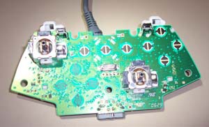
Analog sticks work by adjusting two potentiometers (pots). After I took the controller all apart and experimented I found the potentiometers had an upper voltage of 1.61 volts and a lower voltage of 0 volts. On the up/down pot all the way up is 1.61 volts and all the way down is 0 volts. On the left/right pot all the way right is 0 volts and all the way left is 1.61 volts.

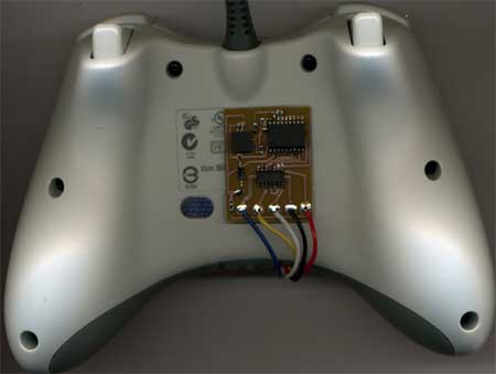
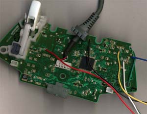
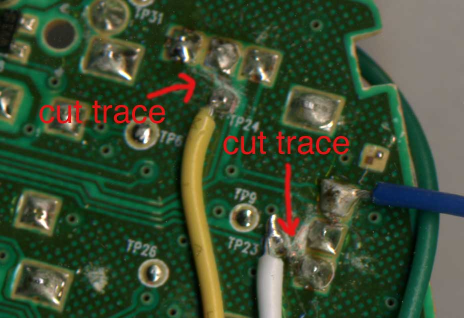
Luckily the output voltage from each pot is easily accessible as they have included a test point. I need to simply solder into the test point and I can send my own voltages to the brains of the controller. The test point for the up/down pot is TP23. The test point for the left/right pot I will know as soon as I figure out how to take off the triggers without breaking them…

My next step will be to solder wires to the board at the points I need them and learn how to use an accelerometer as a tilt sensor. I also need to do some research to determine what to use for my digital to analog conversion. I usually use a PIC16F88 for my projects, but it does not have a DAC.